
Inverter current, I (A) in amperes is calculated by dividing the inverter power, P i (W) in watts by the product of input voltage, V i (V) in volts and power factor, PF.
From the late nineteenth century through the middle of the twentieth century, DC-to-AC was accomplished using or sets (M-G sets). In the early twentieth century, and began to be used as switches in inverter circuits. The most widely used type of tube was the.
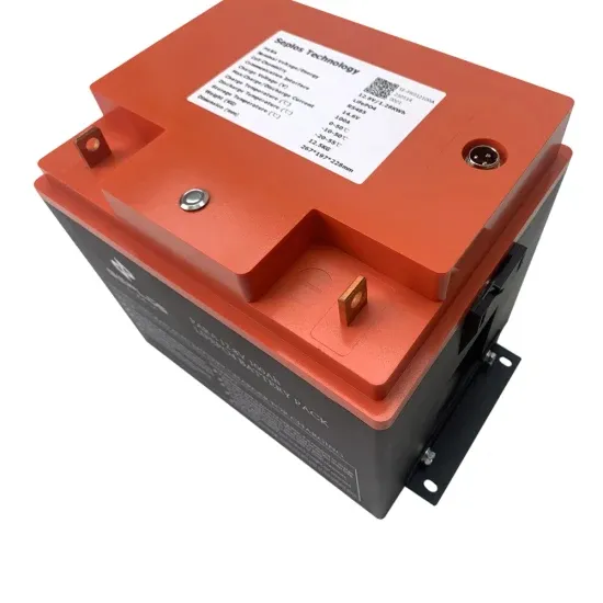
The inverter's voltage must match the battery system's nominal voltage. 12V, 24V, 48V-they have to be the same. If you only learn one thing from this page, this needs to be it.
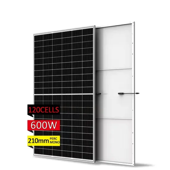
Solar inverters may have a minimum operating voltage, so wiring in series allows the system to reach that threshold. When wired in parallel, the amperage increases while the voltage stays the same, allowing you to produce the energy you need without exceeding the inverter's voltage.
If the voltage from the solar array or battery bank drops too low by the time it reaches the inverter terminals, the inverter may register a fault and shut down. This is a common cause of 'nuisance tripping,' where the system stops working even though there is ample sunlight.
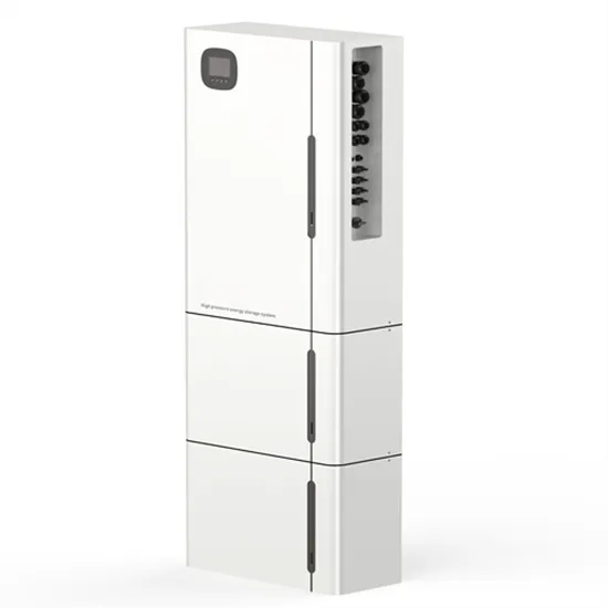
This diagram outlines the necessary connections between the panels, batteries, and other components to ensure a properly functioning system. The PV solar panel wiring diagram provides a visual representation of the electrical circuit for your solar panel.
● Charging Voltage: Also known as the fully charged voltage, this is the maximum safe level, up to 3. 65V per cell, used to charge the battery. Exceeding this can cause irreversible damage.
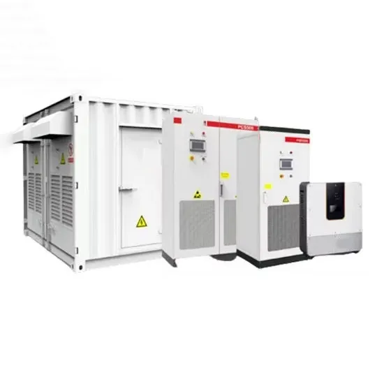
E-START ENERGY delivers utility-scale BESS for frequency regulation, peak shaving, electricity market participation, and grid-side solutions. Request a free consultation and get a custom quote for your project — from 1MW to 500MW+.
Have questions about grid-scale energy storage, frequency regulation systems, peak shaving solutions, or grid interconnection technology? Reach out – our energy storage experts are ready to assist.