
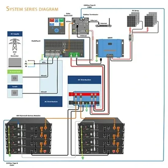
A conceptual power train schematic diagram below illustrates the principles of operation of a three-stage grid tie inverter. Such a topology can be useful for low-voltage inputs (such as 12V) in grounded systems. The control circuits and miscellaneous details are not shown.
Summary: A 12V 10A inverter can theoretically deliver 120 watts of power, but real-world efficiency and device requirements significantly impact performance.
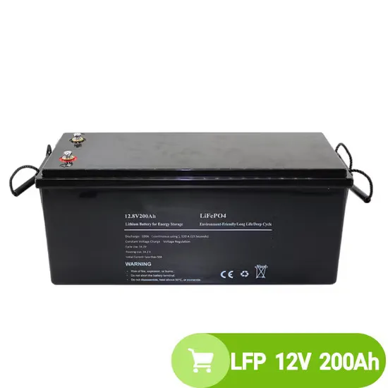
Summary: A 12V battery can typically power inverters ranging from 300W to 3000W, depending on its capacity and discharge rate. This guide explains how to calculate wattage limits, optimize runtime, and avoid common mistakes when pairing batteries with inverters.
While the basic calculation suggests 100A for a 12V 1200W inverter, real-world needs typically range 105-120A. Always consider efficiency ratings, peak loads, and system design for optimal performance.
A quick rule is to divide watts by 10 for 12V systems or 20 for 24V systems. For more accuracy, divide the load by the actual battery voltage and adjust for inverter efficiency (typically 85%).
Quick answer: 300W at 12V draws 25 Amps. But in reality, you should plan for about 30 Amps to cover efficiency losses. The calculation itself is straightforward.
There are several methods used to implement reverse - polarity protection in 220V to 12V inverters. A diode allows current to flow in only one direction.
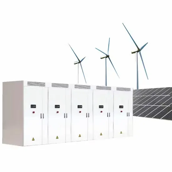
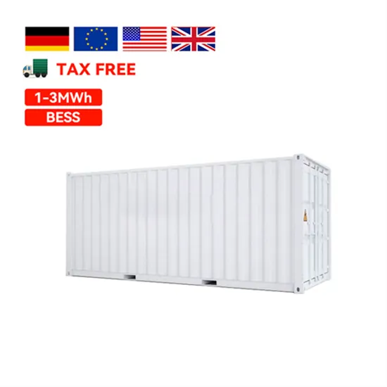
E-START ENERGY delivers utility-scale BESS for frequency regulation, peak shaving, electricity market participation, and grid-side solutions. Request a free consultation and get a custom quote for your project — from 1MW to 500MW+.
Have questions about grid-scale energy storage, frequency regulation systems, peak shaving solutions, or grid interconnection technology? Reach out – our energy storage experts are ready to assist.