
From the late nineteenth century through the middle of the twentieth century, DC-to-AC was accomplished using or sets (M-G sets). In the early twentieth century, and began to be used as switches in inverter circuits. The most widely used type of tube was the.
Inverter current, I (A) in amperes is calculated by dividing the inverter power, P i (W) in watts by the product of input voltage, V i (V) in volts and power factor, PF.
Inverters output an AC signal that is typically either a sine wave, square wave, or modified quasi-sine wave, depending on the application. Inverter signal outputs that aim to replicate mains power are commonly 50 or 60 Hz at 120 or 240 VAC to match standard power line frequencies and.
This article offers a comprehensive review of state-of-the-art current-limiting tech-niques for GFM inverters and outlines open challenges where in-novative solutionsare needed.
Engineers have designed inverters to vary the resistance and continuously find new maximum power point (MPP) in a circuit; this is called maximum power point tracking (MPPT). An inverter can be hooked up to one or many PV panels at a time.
Protection at startup: Inrush Current Limiters prevent potential damage to electronic components by limiting excessive surge currents. Different technologies: NTC thermistors, PTC thermistors, and fixed resistors each provide unique benefits for specific applications.
To determine the required amps for your inverter, you can use the formula: Watts / Volts = amps. It can be useful for selecting an appropriate battery size or determining the necessary volts for your.
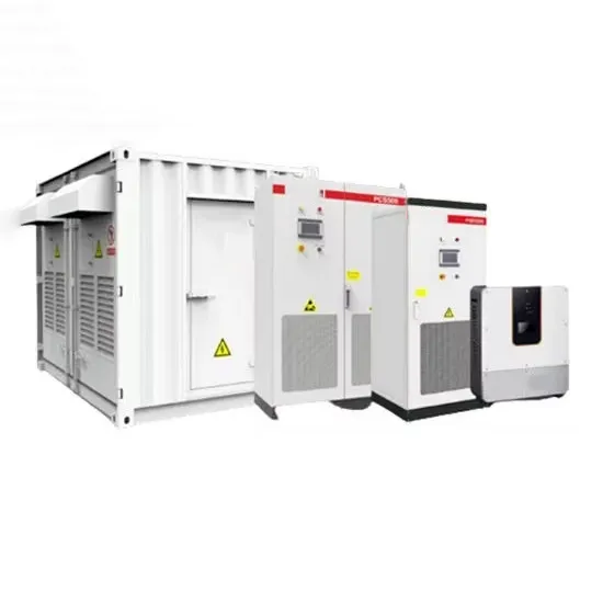
E-START ENERGY delivers utility-scale BESS for frequency regulation, peak shaving, electricity market participation, and grid-side solutions. Request a free consultation and get a custom quote for your project — from 1MW to 500MW+.
Have questions about grid-scale energy storage, frequency regulation systems, peak shaving solutions, or grid interconnection technology? Reach out – our energy storage experts are ready to assist.