
From the late nineteenth century through the middle of the twentieth century, DC-to-AC was accomplished using or sets (M-G sets). In the early twentieth century, and began to be used as switches in inverter circuits. The most widely used type of tube was the.
Inverter current, I (A) in amperes is calculated by dividing the inverter power, P i (W) in watts by the product of input voltage, V i (V) in volts and power factor, PF.
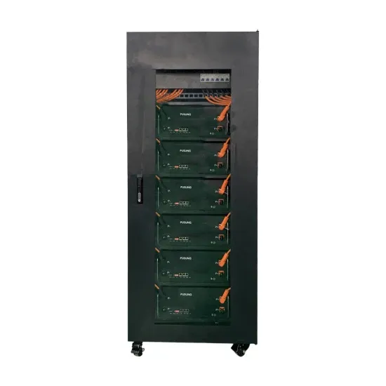
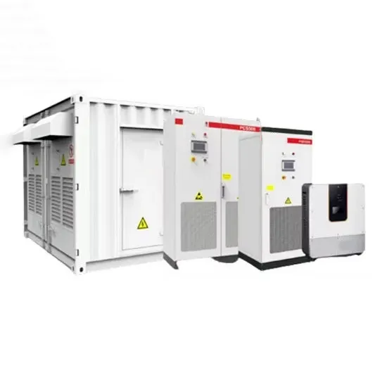
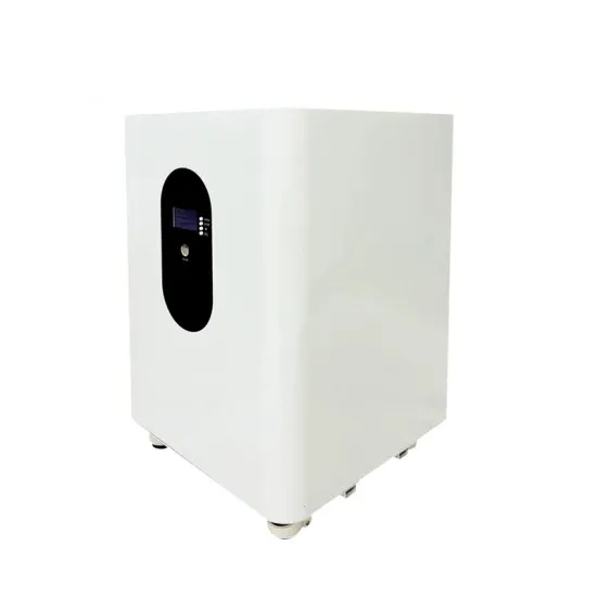
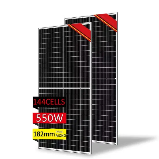
This project combines high-capacity lithium battery storage, advanced hybrid inverters, and next-generation PERC solar panels to provide clean, reliable, and cost-effective power in a region This central inverter has an advanced circuit topology and long-life components.
Overloading the inverter regularly can negatively impact its efficiency and overall performance. It may lead to voltage fluctuations, increased power consumption, and shorter lifespan.
Once the inverter is powered on, measure the AC output voltage using a multimeter. It should match your region's grid voltage (commonly 110V-120V or 220V-230V). Next, connect an oscilloscope to observe the waveform.
The current drawn is approximately 104. Understanding how much current your inverter draws is vital for several reasons: Battery Bank Sizing: Knowing the current helps determine how many batteries you need and how long they will last. Cable Sizing: Undersized cables can.
In this article, I will take you on a journey through the essential role of PWM in single-phase full-bridge inverters, explore different PWM techniques, and share real MATLAB simulation results that bring theory into life. Let's dive in!.
E-START ENERGY delivers utility-scale BESS for frequency regulation, peak shaving, electricity market participation, and grid-side solutions. Request a free consultation and get a custom quote for your project — from 1MW to 500MW+.
Have questions about grid-scale energy storage, frequency regulation systems, peak shaving solutions, or grid interconnection technology? Reach out – our energy storage experts are ready to assist.