
The wiring diagram will indicate where these fuses or circuit breakers need to be located in the combiner box. Additionally, the diagram will show the wiring connections for the positive and negative terminals of each string of solar panels and the wires.
In this very basic solar panel wiring installation tutorial, we will show how to connect a solar panel to the AC load through UPS/Inverter, charge controller.
See a complete example solar panel wiring diagrams done by Ecuip Engineering & Solar Design Lab here: Download Example Solar Panel Wiring Diagram. See a complete example solar panel wiring diagrams done by Ecuip Engineering & Solar Design Lab here: Download Example Solar Panel Wiring Diagram.
It is a grid-tied inverter with a maximum power output of 35,000 watts, making it suitable for larger installations. The inverter is compatible with both monocrystalline and polycrystalline solar panels, providing flexibility in system design.
When you switch on the first things you will notice on a solar inverter screen battery voltage and output voltage positioned at the top. Below it,The entire system diagram is shown with flowing arrows, which indicates the current operational condition of each solar system.
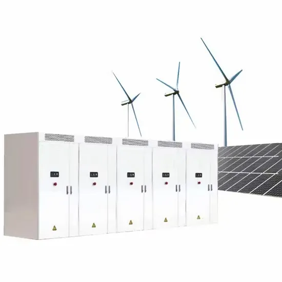
To go solar, you'll need solar panels, inverters, racking equipment, and performance monitoring equipment--at a minimum. Depending on where you live, you may also consider a solar battery.
A conceptual power train schematic diagram below illustrates the principles of operation of a three-stage grid tie inverter. Such a topology can be useful for low-voltage inputs (such as 12V) in grounded systems. The control circuits and miscellaneous details are not shown.
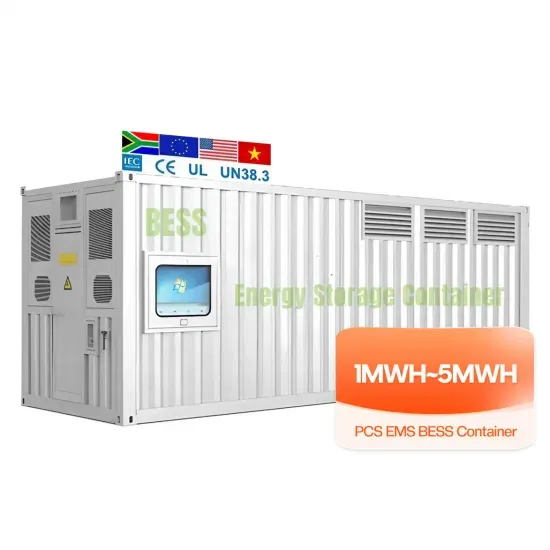
E-START ENERGY delivers utility-scale BESS for frequency regulation, peak shaving, electricity market participation, and grid-side solutions. Request a free consultation and get a custom quote for your project — from 1MW to 500MW+.
Have questions about grid-scale energy storage, frequency regulation systems, peak shaving solutions, or grid interconnection technology? Reach out – our energy storage experts are ready to assist.