
The wiring diagram will indicate where these fuses or circuit breakers need to be located in the combiner box. Additionally, the diagram will show the wiring connections for the positive and negative terminals of each string of solar panels and the wires.
A conceptual power train schematic diagram below illustrates the principles of operation of a three-stage grid tie inverter. Such a topology can be useful for low-voltage inputs (such as 12V) in grounded systems. The control circuits and miscellaneous details are not shown.
Whether you are an experienced DIY enthusiast or a beginner, this step-by-step guide will provide you with a clear understanding of the solar panel installation process.
A free online tool to easily create, customize, and export professional solar power system diagrams. Drag and drop components, connect lines, and save your work.
Overload test and short circuit test are used to test the performance of grid tie micro inverters under abnormal working conditions; overvoltage test is used to test the protection ability of micro inverters under high input voltage; lightning protection test is used to.
For solar inverter applications, it is well known that insulated-gate bipolar transistors (IGBTs) ofer benefits compared to other types of power devices, like high-current-carrying capability, gate control using voltage instead of current and the ability to match the co-pack.
Our advanced inverters convert solar energy into usable electricity with seamless efficiency. Choose from grid-tied, hybrid, or off-grid models to match your energy needs.
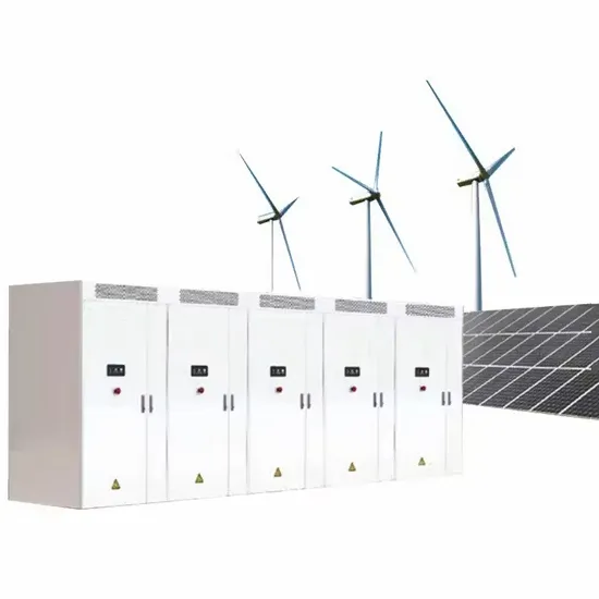
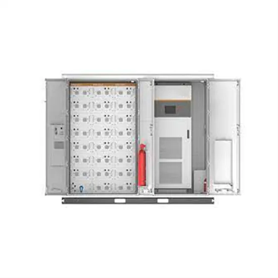
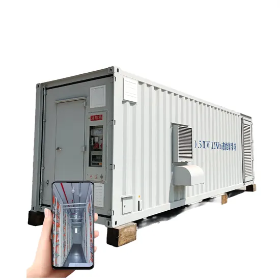
E-START ENERGY delivers utility-scale BESS for frequency regulation, peak shaving, electricity market participation, and grid-side solutions. Request a free consultation and get a custom quote for your project — from 1MW to 500MW+.
Have questions about grid-scale energy storage, frequency regulation systems, peak shaving solutions, or grid interconnection technology? Reach out – our energy storage experts are ready to assist.