

Section II of this paper describes the approach taken for PV inverter modeling including the response of the PV inverters grid synchronization control elements.
The invention discloses a phase sequence detection method of a three-phase grid-connected photovoltaic inverter, which is characterized in that: 1, a Uab and a Ubc are set as voltages of a sampled two-phase wire, and are subjected to Clarke conversion to obtain the Alpha.

In this article, I will take you on a journey through the essential role of PWM in single-phase full-bridge inverters, explore different PWM techniques, and share real MATLAB simulation results that bring theory into life. Let's dive in!.

This is caused by low intermediate circuit DC voltage. This can be caused by a missing supply voltage phase from a blown fuse or faulty isolator or contactor or internal rectifier bridge fault or simply low mains voltage. POSSIBLE FIXES: Check mains supply and fuses.
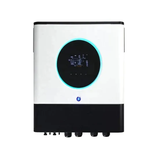
The working principle of the inverter is to use the power from a DC Source such as the solar panel and convert it into AC power. This conversion process can be done with the help of a set of IGBTs (Insulated Gate Bipolar.
Open-circuit voltage, or Voc, is the maximum voltage a solar panel can produce when not connected to an electrical circuit. It's like a river at its highest point, ready to cascade down when released. With no electrical load, there's no current, and the voltage soars to its.
A conceptual power train schematic diagram below illustrates the principles of operation of a three-stage grid tie inverter. Such a topology can be useful for low-voltage inputs (such as 12V) in grounded systems. The control circuits and miscellaneous details are not shown.
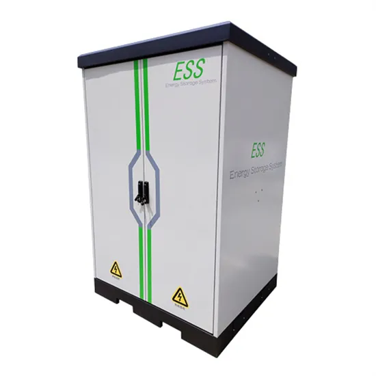
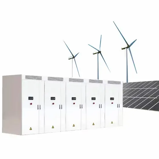
E-START ENERGY delivers utility-scale BESS for frequency regulation, peak shaving, electricity market participation, and grid-side solutions. Request a free consultation and get a custom quote for your project — from 1MW to 500MW+.
Have questions about grid-scale energy storage, frequency regulation systems, peak shaving solutions, or grid interconnection technology? Reach out – our energy storage experts are ready to assist.